quarta-feira, 25 de março de 2009

LED center

LED center

PWM Fan controller


PWM or Pulse Width Modulation has generally been regarded as too complicated for PC fan speed control compared against using rheostats or linear voltage regulators such as the LM317. I present here a PWM circuit that is simple and cheap enough to be built by the casual electronics builder.

Why would you want to use PWM instead of a rheostat or voltage regulator? Well, like most things, each method has it's own strengths and disadvantages:

Rheostats


Pros: Cheap and easy to use.

Cons: Difficult to find suitable rheostats, introduces current limiting causing the fan to fail to start or stall at slow speed settings.


Linear voltage regulators


Pros: Does not have rheostat like current limiting, temperature control can be incorporated.

Cons: Regulator can generate considerable heat which limits the maximum fan power. (The more powerful the fan, the more heat is generated), maximum output voltage to the fan can be several volts less than the supply limiting the maximum cooling from the fan. (A by-pass switch can be fitted to eliminate this problem, but this adds to the complexity of the circuit).


PWM


Pros: As linear voltage regulator, plus comparatively little heat is generated by the circuit allowing higher powered fans to be used, output is virtually 0-100%, eliminating the need for a bypass switch, fans do not stall or fail to start at minimum fan speed.

Cons: The fan speed sensing is disabled, can cause "growling" noises at very low speed settings with some fans.


What is PWM? In simple terms, PWM involves rapidly switching the supply to the fan on and off, in this case 30 times a second, (30Hz). By altering the relative on to off times the average voltage "seen" by the fan is also altered. E.G. Assuming a 12V supply, when the on/off ratio = 50%/50% the fan will "see" 6V, likewise when the on/off ratio is 75%/25% the fan "sees" 9V. Obviously 100% output is achieved by having the output on continuously and at 0% the output is off. It is this on/off switching that makes the fan speed sensor inoperative.

The circuit uses a purpose made chip, MIC502 made by MICREL. Fan speed is adjusted by varying VR1. With the component values shown the output is 40%-100%. ( 4.8 - 12V). So far every fan I have tested runs at 4.8V. To guarantee the fan starts when the computer is switched on, the chip automatically runs the fan at full output for approximately 2 seconds before dropping to the preset speed. Changing the value of R1 and R2 to 7K5 ohms will give an output range of 0% - 100%.

If desired, R1 and R2 can be replaced with 22K variable preset resistors to allow exact tailoring of the control range. Varying R1 will alter the maximum output, whilst R2 controls the minimum. Note these adjustments are interactive with each other and will require some trial and error to achieve the desired range. The diode, D1 is to protect the transistor from reverse voltage spikes when switching the fan off. Using modern DC axial fans should not be a problem and D1 may be considered optional. Since I cannot test every possible device people may connect to the circuit I have included D1 for completeness.

On the other hand, the decoupling capacitor, C2 is NOT optional. During testing it became apparent that the chip does not like "noisy" supplies. E.G. My 350W " Enermax has very long leads and poor quality connectors. This does not help maintain a clean supply. Things may be different for you but I consider C2 to be necessary. C1 sets the pulse frequency, in this case 30Hz.

During testing "growl" noise at low speeds was not a problem. If "growl" is a problem with your specific fan then changing the value of C1 should help. Use the formula C = 3/f where C is in microfarad (uF) and f is the desired frequency in hertz (Hz). Try frequencies in the range 30-100 Hz. R4 limits the base current to the transistor T1. T1 is rated at 5A which equates to 60W of fan!! In practise the circuit should be capable of running any reasonable number of case fans. With several powerful fans connected the transistor may get warm so a small heatsink may be required.

Several channels can be made to make a multi channel fan bus. Only one "C2" is required if all the channels are built on the same board. Looking at the circuit diagram, the "+12V" and "0V" terminals connect to the respective connections on the PSU Molex connector. The "FAN+" and "FAN-" connect to the corresponding +v and -v terminals on the fan.

PWM Fan controller Simple PWM Fan Controller

Adding Temperature control.
PWM Fan controller Simple PWM Fan Controller
Here the resistor R1 has been replaced with a thermistor to give temperature control. The fan speed is set by VR1 and as the temperature rises, so the fan speed will increase to compensate.

PWM Fan controller Simple PWM Fan Controller
This version is identical to the temperature control above, except for the addition of a "sleep" setting. The idea is to turn the fan off when the temperature falls below the value set by VR2.

Building the circuit.

PWM Fan controller Building the circuit
Here is an example of the built circuit on a small piece of stripboard. The 2p coin gives an indication of size. I have not included the diode D1 in this example.

PWM Fan controller Building the circuit
Side view.

PWM Fan controller Building the circuit
General layout of components.

PWM Fan controller Building the circuit
Under side of the board showing the breaks in the stripboard tracks. Note the use of solder bridges to link leads on IC1.

PWM Fan controller Building the circuit
Underside of the board showing component locations.

Component List: figures in brackets are Rapid Electronics stock codes.
IC1 = MIC502BN (82-4026)
T1 = TIP122 (81-0172)
D1 = 1N4001 (47-3420)
R1 = 10K (62-2146)
R2 = 15K (62-2154)
R4 = 270R (62-2070)
VR1 = 10K Linear (65-0715)
VR2 = 47K Linear (65-0725)
Thermistor = (61-0515)
C1 = 0.1uF (10-3220)
C2 = 220uF 25V (11-0265)

Matrix Orbital MX610 LCD display

Matrix Orbital MX610 LCD display Introduction

When most think of drivebay LCD displays, they think of just one company: Matrix Orbital. With good reason too - they make some of the best programmable LCD displays on the market, and have been doing so for the past decade. It is nearly 4 years now since bit-tech reviewed Matrix Orbital's first PC-based products, and we have closely followed their progress ever since.


Matrix Orbital MX610 LCD display Introduction Matrix Orbital MX610 LCD display Introduction
Matrix Orbital displays have featured in a number of our big case mod projects over the years: most people would instantly recognise
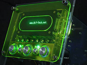
 Orac³ and 
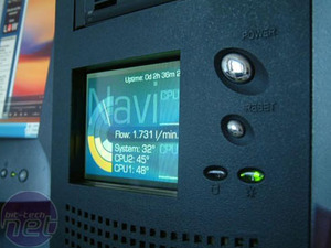
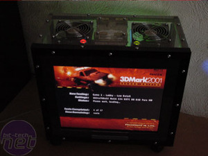
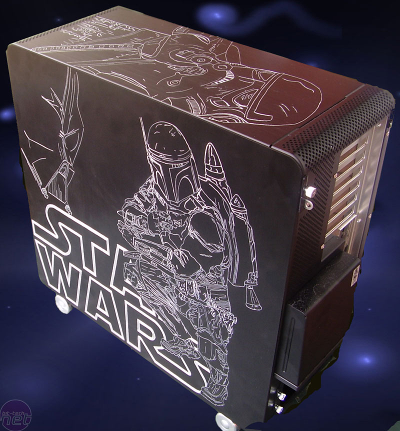
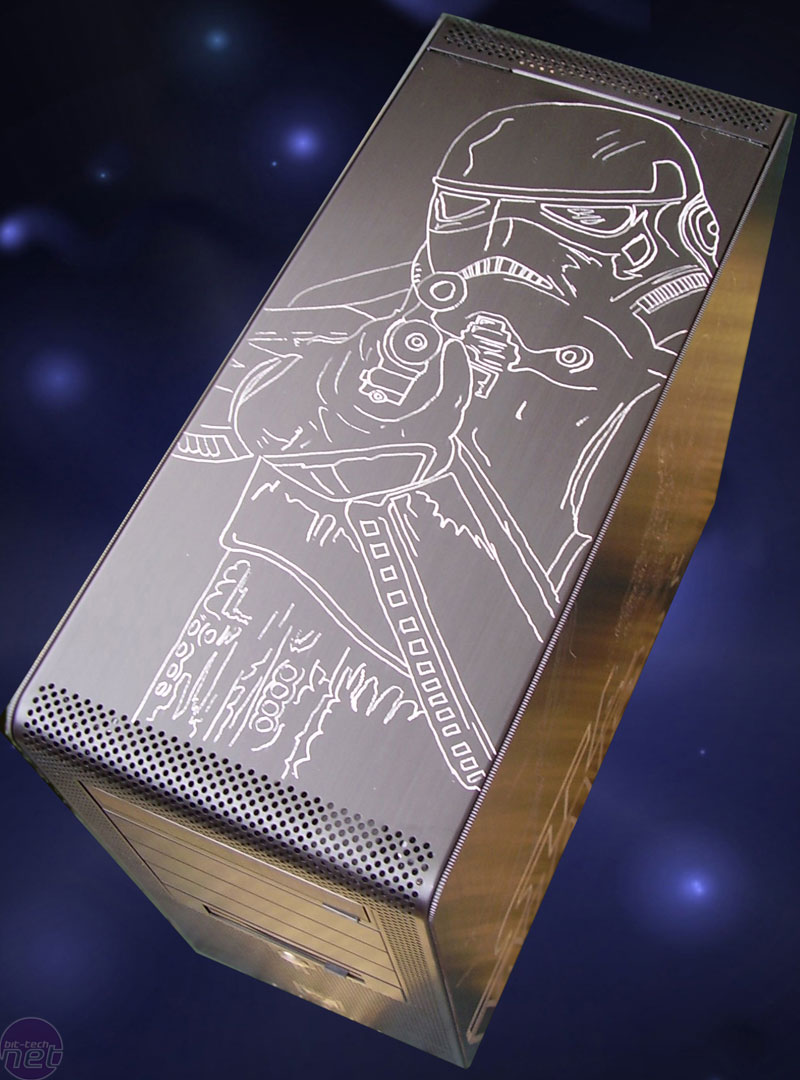
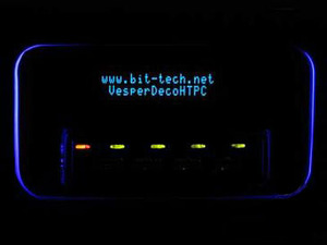
Vesperdeco (pictured) and resident Grand-daddy of modding, Dave 'Macroman' Williams, is a fan, employing them for both Project 3G Clear and Macro Black. Over the years, there has been no finer LCD display than a Matrix Orbital.


What the modders innovate, the mainstream imitate

While the hardcore modders live on the bleeding edge, blowing up various components at their own expense in the pursuit of their latest mad invention, there is an entire industry of mainstream manufacturers trawling the internet trying to spot the next must-have product in waiting.

Take LEDs fans and window-modded cases. To modders, they are so 2001, but walk into any mainstream computer store these days and you will see that both concepts are now truly mainstream. Blowholes? Rounded cables? Watercooling? All have the modding community to thank for daring to wonder 'What If?', one rainy Saturday afternoon, years ago.


Matrix Orbital MX610 LCD display Introduction Matrix Orbital MX610 LCD display Introduction
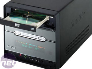
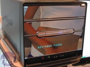
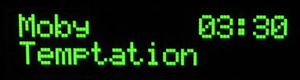
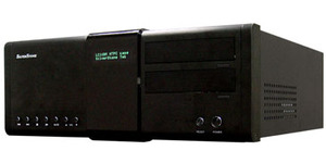
Naturally, the idea of front-mounted LCD displays aren't immune to this process, and Shuttle have recently incorporated a VFD to the front of their Media Center-ready SB85G5M barebones, set to display song titles, DVD timecodes and other useful information. Naturally, we found a couple of hidden uses when the case was shown to us at Computex 2005. Shuttle have also used the same VFD in their just-announced XP Media Center.

Matrix Orbital MX610 LCD display Introduction
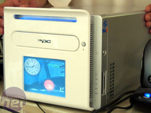
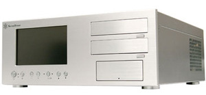
Of course, such displays are becoming quite commonplace, thanks to the explosion in the Home Theatre PC market. 
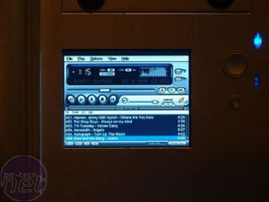
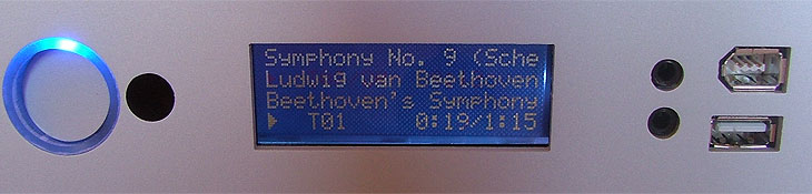
beblu's Media Center has a neat, four line LCD which displays all the information you need in clear, white text on a blue background. Information like track title and duration are automatically output to the LCD by Media Center.

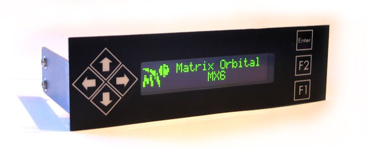
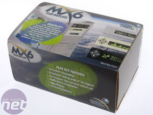
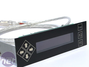
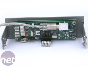
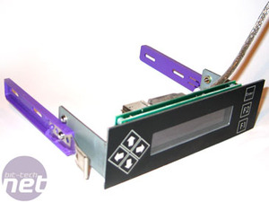
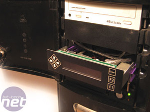
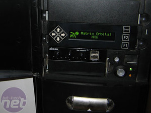
With front-mounted LCD displays now firmly in the mainstream, are the days of the discrete, programmable LCD display numbered? We grabbed the most recent model from Matrix Orbital, th MX6, to find out.
Matrix Orbital MX610 LCD display Introduction

he Bundle

Matrix Orbital MX610 LCD display The Bundle Matrix Orbital MX610 LCD display The Bundle
First impressions are good. The display comes packed securely in a very sturdy box, so wherever you live on this blue planet of ours, you can be sure your MX6 will arrive in one piece. Sadly, the same cannot be said of every sample we receive. Everything comes neatly bagged, and the display itself has an extra layer of bubble wrap just to be safe.
Matrix Orbital MX610 LCD display The Bundle Matrix Orbital MX610 LCD display The Bundle
The model we received dispenses with the old RS232 serial interface for the more modern USB. As standard, the MX6 comes with a USB cable which loops out the back and into a rear USB port (see installation). If you have internal, on-board USB headers on your motherboard, you can order the optional internal USB cable. This gives a neater result, and saves you a rear port. Both cables are sleeved in sexy silver braiding. Also from the options list is a pair of external temperature probes.

Matrix Orbital MX610 LCD display The Bundle Matrix Orbital MX610 LCD display The Bundle
Straight out of the box, the MX6 displays the usual Matrix Orbital quality. Solidly built, it weighs a purposeful 180g or so with USB cable - this is certainly no cheap, flimsy Made In China plastic garbage. The chassis is made from 2mm steel and doesn't bend under stress. This model - the MX610 - has the multi-function keypad, but you can also buy the same display with a plain bezel for a cleaner look (MX620 / 630).

All displays in the MX6 series are 20 x 2, meaning there are two rows of 20 characters. Unlike many other Matrix Orbital displays, which use a Vacuum fluorescent display (VFD), the MX6 uses a Polymer LED screen. PLED has the advantage of lower power consumption, a very wide viewing angle (160 degrees) and a fast response time / pixel refresh rate.
Matrix Orbital MX610 LCD display The Bundle Matrix Orbital MX610 LCD display The Bundle
Moving around to the rear reveals the inner workings. The PCB is in two layers: the first is dedicated to driving the display, while the outer layer handles I/O. On the left are three channels for the temperature probes, while next to it are three General Purpose Outputs (GPOs) which can be used for fans. There is also a floppy drive power connector if more power is required than the USB port can provide - 150mA for an unpowered hub; 500mA from a high powered USB port.

Hardware installation

The physical installation, at least in theory, couldn't be easier - just plug it into a USB port, and you're done. In reality, the quirks of our test rig made things a little more challenging.

The first obvious issue is that we have an Antec Sonata - an all round great case by all means - however, it has a door that stealths the drive bays. Fortunately, it can be removed, but in truth, any front-mounted LCD like the MX6 is far better suited to doorless cases like the Lian Li PC60 we used for Project Synapse.

The second issue is more serious. The Sonata, and many other cases, employs quick release rails for its 5.25" drive bays: screw them to your DVD drive, and you can slide it in / out just by pinching the tabs. This means none of the usual mucking around with mounting screws, and wondering if you put any on the far side that you can never reach. This is a problem because the mounting tabs on the MX6 are only only 60mm long - long enough to line up with the first row of mounting holes on a conventional case.


Matrix Orbital MX610 LCD display Installation Matrix Orbital MX610 LCD display Installation
The solution was only partially successful: mount the rails as normal, using only the first set of holes, and just tighten the screw really tightly. The display slides into place and the tabs lock into place, but not securely enough to press the keypad buttons without the whole assembly sliding back inside the case. Prospective buyers with quick release cases like the Sonata might want to consider their mounting options carefully.


Matrix Orbital MX610 LCD display Installation Matrix Orbital MX610 LCD display Installation
As mentioned earlier, the standard design uses a loop-through USB cable, passing out through an empty PCI backplate and into a rear USB port. If your computer room is as dusty as ours, we'd strongly recommend opting for the internal USB cable and keep that rear PCI plate screwed in place. With power applied, we are greeted by a funky welcome message.


Software installation

The software installation was far easier, thanks to USB.

Matrix Orbital MX610 LCD display Installation Matrix Orbital MX610 LCD display Installation
Just pop the mini CD into the drive (slot-loading users beware!) and participate in the familiar Next - Next - Next - Finish ritutal. The MX6 was detected first time, and the drivers on the CD worked like a charm. Now that Windows knows it's there, it was time to install some software to make it display something useful.

Matrix Orbital MX610 LCD display Installation
Matrix Orbital bundle LCDC, which would otherwise cost US$19.50 +VAT. LCDC is what you use to program the MX6 (and all other Matrix Orbital displays) to display information on the screen. 'Program' is the operative word - as we will discover, this is no fluffy, Wizard-driven application. Gone are the days when such displays required Visual Basic skills to program your own interface, but users expecting a friendly GUI with simple menu options will very quickly break into a nervous sweat and start reaching for the PDF manual.

Let the fun begin...

LCDC Tutorial

The heart of LCDC revolves around the Screen Builder. Here you can define one, or several, screens to display on your MX6. The can be pure text or you can design your own logos. Using plugins available for common programs such as Winamp, you can import variable such as Track Name and Time Remaining to design your own interface. Here is a simple, plain text example:

Matrix Orbital MX610 LCD display LCDC Tutorial Matrix Orbital MX610 LCD display LCDC Tutorial
click for full size
Having created a blank screen, we can name it, set its duration, frame rate and decide on the transition between this screen and any subsequent one. The Fade in/out is particularly sexy. Moving to the Lines screen, we simply type into the text box for Line 1 and Line 2 respectively and set variables like Alignment and Scroll. The text appears on the display as you type it:

Matrix Orbital MX610 LCD display LCDC Tutorial

Moving on to something more useful, we created a quick Winamp screen to display our music information. There are a few pre-defined screens included with the software - to display the time for example - but we preferred to make a custom Winamp screen.

Matrix Orbital MX610 LCD display LCDC Tutorial Matrix Orbital MX610 LCD display LCDC Tutorial
click for full size
Matrix Orbital MX610 LCD display LCDC Tutorial
Again, using Screen Builder, it was a case of selecting the desired information and inserting it into the location on either line. This is where things start to get a little crazy: the line text becomes a series of barely intelligable codes, and the madness doesn't stop there. We thought it would be fun to convert the new bit-tech logo into the right format to display on the MX6.

After much frustrating research, we discovered we were missing a program: Char Mapper. Rather than a nice bitmap conversion program, to display a graphic or logo using LCDC, you have to create a Custom Character set with the image chopped up into the appropriate 5x8 pixel chunks per character.

Matrix Orbital MX610 LCD display LCDC Tutorial

Matrix Orbital MX610 LCD display LCDC Tutorial
To build the logo, the letters 'bit-tech' were entered on Line 2 in plain text. We then imported the Custom Character set created using Char Mapper, which features the round logo and 'dot net' text using 5x2 blocks. The end result is far from perfect, and the creation process was arduous: filling in each pixel in Char Mapper using Photoshop as a guide, having overlayed a grid on our logo JPG in the image editing software. After lots of edits and resaving the character set, we discovered a new-found respect for the people who contributed many of the pre-defined screens available for download from the LCDC gallery.

While there is a Motherboard Monitor plugin, and can directly support three temperature probes, we found the work required to build the necessary screens and programming the GPOs using LCDC to be more work than it should be. Anyone just wanting to know the temperature of their PC's innards would be better buying a cheap LCD probe for a quarter of the price.

We got there in the end, but the experience raises an interesting question: would you rather total control or ease of use?

LCDC will allow you to output virtually anything to the MX6, but Matrix Orbital themselves admit that 'the learning curve is steep'. For many enthusiasts, programming innovative new screens is part of the experience - many feature clever animations and other advanced tricks. However, for the part-time geek just wanting to put a cool LCD on the front of his HTPC, having to program things themselves will be daunting.

There is, of course, an active LCDC Community on hand to help out new users, but we would have preferred to see more pre-defined work included on the CD, and an easier-to-use way to display the most common functions than using the overly complicated LCDC.

Alternatives

There are now a number of options available for users wanting to display information on the front of the computer; options that didn't exist 4 years ago when Matrix Orbital first became popular with modders. Before we can pass judgement on the MX6, we need to look at the alternatives.

Option A: PSOne LCD mod

Cost: £26.99 / US$34.99
From: eBay
Difficulty: Moderate

bit-tech regular Brian Walker aka bEE2643 was one of the first people to perform this mod, way back in July 2004. Essentially, it involves buying a cheap Sony PSOne LCD from eBay, stripping it down, mounting the display somewhere cool, and hooking it up to the TV-Out of your graphics card. We have a detailed article titled PSOne LCD in a PC and the related Forum Thread has become a central meeting point for many modders to ask questions and help each other.

Matrix Orbital MX610 LCD display Alternatives Matrix Orbital MX610 LCD display Alternatives
4 hours later, and you have your own 5-inch, 640x480 TFT capable of displaying anything your heart desires. You just set it as your secondary display, and you can use an extended desktop to position any window into place. Winamp is naturally a popular option. Alternatively, you can use Samurize to display some seriously funky stuff, like Nexxo's Project Metaversa (right), detailing crucial temperature and waterflow information.


Option B: In-car LCD mod

Cost: £60-150 / US$120
From: eBay or various stores
Difficulty: Moderate

This mod is very similar to the PSOne mod above, but uses more sophisticated LCDs designed for in-car DVD systems. Most are 7-8 inches across and many are 16:9 widescreen. The more expensive ones even have touchscreens. Specifications vary wildly, with resolutions as low as 320x240, but KustomPCs sell a one capable of 800x480. eBay is a good source, though most sellers ship directly from Hong Kong or China, so it isn't for the timid.

Matrix Orbital MX610 LCD display Alternatives Matrix Orbital MX610 LCD display Alternatives
Mounting options are similar to the PSOne mod. One cool option would be to buy a motorised in-dash screen and mount it in a drive bay under your DVD writer. One touch of the button, and out pops the LCD - the ultimate LAN party showboating feature. Abbas Jaffarali at Tbreak.com gets a special mention for creating a really nice example using a Shuttle SB86i and a 5-inch car LCD.


Option C: 14"-17" TFT monitor mod

Cost: from £100 / US$170
From: NewEgg or various stores
Difficulty: Moderate

Now that desktop LCD prices have fallen through the floor, turning an entire [/i]side[/i] of your PC into a display is now within the budget of many modders. bit-tech forum regular, CharlieCat, is a veteran at this one - he has now created three systems using this technique.

Matrix Orbital MX610 LCD display Alternatives Matrix Orbital MX610 LCD display Alternatives
Depending on the size of your case, and the size of your budget, you can pick up a bargain 15" LCD for around £100; NewEgg has several models for US$170. The resolution will be 1024x768 and the viewing angle will be pretty rubbish, so you might be better off saving up a few extra pennies and plumping for a 17" model. Just £125 / $200 will net 17 inches, 1280x1024 and a 12ms refresh rate.


Option D: New case with LCD

Cost: from £188 to £500
From: Kustom PCs or Scan
Difficulty: Easy

There are off-the-shelf options, including the Shuttle and beblu systems already mentioned, the latter available in a case-only option. Another leading manufacturer in this field is Silverstone - they make several cases that feature bezel-mounted VFD displays similar to the Matrix Orbital's range.

Matrix Orbital MX610 LCD display Alternatives Matrix Orbital MX610 LCD display Alternatives
Most of the range have a stylish A/V receiver-look to their appearance, like the LC14BM (left). Truthfully, they are all available without VFD also, for considerably less. The most famous Silverstone case of them all is the LC18 (right), which sports a 7" touchscreen LCD on the front bezel as standard. However, at £500 from Scan, you certainly pay a premium for not doing the work yourself.

Conclusions

Back when this trend began, your choice was simple: Matrix Orbital or Crystal Fontz. The concept was new, so high prices, small sizes and DIY software was part of the adventure. However, that was four years ago now and in 2005, our expectations are vastly different.

Matrix Orbital displays have always been extremely well made but also expensive, and this extends to the MX6. US customers will pay US$109.99 for the display plus accessories. KustomPCs sell them in the UK, but with the extra shipping and VAT, the price blows out to £76. However, the 20 x 2 configuration of the MX6 is somewhat limiting: it occupies a full 5.25" drive bay, yet you can only display 2 lines of text at a time.

We found most of the community-made screens and animations aimed at the larger 20 x 4 models, showing that most customers (quite rightly) prefer the extra real estate of the four-line displays. Matrix Orbital don't offer a four-line PLED display, so by the time you switch to the more expensive VFD technology and supersize an extra 2 lines, you're looking at an MX5 for US$149.99 / £98.99.

At that price, you're looking at three times the price of a PSOne LCD mod, and rapidly approaching the budget required for a 15" LCD monitor mod. Even the cheaper two-line MX6 is twice the price of a PSOne project.

You would hope then that Matrix Orbital's software bundle would rescue the situation, but sadly, it too is stuck in a time bubble. There is no denying that LCDC is very powerful. All credit to the LCDC team: for what is essentially a homebrew application, it offers fine control over every facet of the MX6's feature set. Without it, people would probably be left to code their own software.

However, it is far from polished and while we didn't experience any bugs per se, the hoops the user is required to jump through to output information to the screen leave much to be desired. From a usability point of view, it is arguably software designed by programmers, for programmers - code-shy novice users beware.

Considering that HTPC enthusiasts would be a large part of the MX6's target market, it is positively criminal that it is not Media Center compatible. Again, if one had the determination and skill, one could use LCDC to produce your own custom screens to display various HTPC activities. If you were seriously hardcore, you might even code your own Media Center plug-in for LCDC. However, having forked out big bucks for this display, this functionality should be a mere installation wizard away - it should not be down the community to write their own software.

If the MX6 was £20, you might be more forgiving, considering the additional sensor inputs, fan headers and general potential to make it do whatever you want it to do. At four times that price, functionality should be delivered on a silver platter, not be a box full of Lego. Faced with cheaper alternatives with far greater abilities, it is hard to recommend the MX6 to anyone but the most hardcore fanatic.

Case Engraving: Star Wars

Case Engraving: Star Wars Etch-a-Sketch
This article is all about me engraving a Lian Li PCV1000B, to turn it into a Star Wars tribute case. Doing engravings with a Dremel is something that just becomes more and more popular, so after a successful Hellraiser mod, I'm back for another go. I'll be giving some tips and pointers in this article that will hopefully be of some help, and maybe will inspire you to start doing some Dremel-work yourself.

(Editor's Note: If you're interested, you might also like to check out our Engraving - A Modder's How To article.)

Case Engraving: Star Wars Etch-a-Sketch
This is the raw canvas for this project, the Lian Li PCV1000B.


Choosing the image

Choosing the right picture to etch is very important. If you are a beginner try and choose images without any shadows and too much detail - a simple, clean line is a lot easier to get right, so stick to clear, line-based designs. If you want to do something a little more difficult, try adding in some very fine detail. A good way to play with an image is to use Photoshop - you will be able to use the various tools to trace over a very complicated image on a new layer and create a simple line drawing from it.


How do I get my sketch onto the chassis?

When you've got your image printed and ready to engrave, you'll need to apply it to the case so that you have some lines to follow - the easiest way to do this is by using carbon paper. It's a simple technique: put the carbon paper where you want your etch, take the line drawing, and use a (tough) pen to trace over it. This will transfer it to the carbon paper, which is very thin and should transfer the tracing to the case's surface. If you've got some major artistic talent you could do it by freehand, but that is much harder.


Other things to Consider

  • Make sure that you have a good working position - a kitchen table or something like that works fine for me.
  • Don't rush, take it slow and be careful, because one mistake can be the difference between a great engraving and a poor one.
  • If you have some pieces of left-over plexi or even an old chassis, use that for practice before you attack your main case.

Right Side Engraving

Case Engraving: Star Wars The Dark Side
I came up with the idea of doing the Dark Side on the right of the case and the Light Side on the left. On the right, I decided to have Boba Fett.


Case Engraving: Star Wars The Dark Side
Here you can see the clean and clear lines that the carbon paper makes on the case. A good sketch makes it much easier to work with the Dremel on top.


Case Engraving: Star Wars The Dark Side Case Engraving: Star Wars The Dark Side
With Boba Fett done, an evil dude named Darth appears...


Case Engraving: Star Wars The Dark Side Case Engraving: Star Wars The Dark Side
Here's the final result. As you can see engraving on black aluminum gives incredible sharp and crisp lines. This also means that mistakes show too - be careful not to make any big ones! Whilst the engraving might look weird up close, it looks great when seen as a whole.

Left Side Engraving

Case Engraving: Star Wars The Light Side
The original sketch of Yoda on carbon paper had quite a lot of tight detail.


Case Engraving: Star Wars The Light Side Case Engraving: Star Wars The Light Side
Unfortunately, I had to tone down the detail a little when doing the engraving, since the design looked a little too 'busy'. However, with that done, the left side needed something more - another Star Wars logo did the trick. This made Yoda appear more clear and helped to get the right balance in the design.

Time for another coffee break, and then on to the top of the case.

Top Etch

Case Engraving: Star Wars The Light Side Case Engraving: Star Wars The Light Side
This was by far the easiest engraving to do, but it turned out quite well. With an hour's work, an angry Stormtrooper was giving me the evil eye from the top of the case.

The Final result

Here are some candyshots of the finished case:

Case Engraving: Star Wars Final result
You can click the thumbs below for 800px large versions...

Case Engraving: Star Wars Final result Case Engraving: Star Wars Final result Case Engraving: Star Wars Final result
So this was my latest project... I'm sure I'll be busting out the Dremel for some more action very soon!

If you're interested in the tools I used to complete this project, here's the run-down.
  • Dremel Multi Professional.
  • Dremel Flexible shaft.
  • Dremel Diamond engraving bits 7144 and 7134.
  • Pelikan Plenticopy 200h carbon paper.
  • Time, patience and coffee!

A big thanks to Gtek.se for providing the case and making this project possible, you guys rock!

To everyone else i will just say.. Grab your Dremels and make some art!

[i]This article can be found in its original Swedish version at SweClockers.com.

Electrónica

Donde Vem

Downloads

Murros no Estômago

Tecnologia IG Brasil

Baixaki - Downloads

Technow