sábado, 11 de julho de 2009

Inscrições On-Line

Inscrições On-Line
Escola Secundária Augusto Cabrita

Matricula Provisória
(Clica aqui)

2009-2010

Cursos Profissionais de Informática

Inscrições On-Line

Inscrições On-Line
Escola Secundária Augusto Cabrita

Matricula Provisória
(Clica aqui)

2009-2010

Cursos Profissionais de Informática

sexta-feira, 8 de maio de 2009

Lançamento do OpenOffice.org 3.1.0

A Comunidade Portuguesa do OpenOffice.org anuncia hoje a disponibilidade da versão portuguesa do OpenOffice.org 3.1, em simultâneo com as outras versões oficiais. Graças a uma colaboração entre a Sun Microsystems Portugal e a Escola Secundária Augusto Cabrita, e no âmbito de um protocolo de colaboração entre o Ministério da Educação, esta versão portuguesa foi sujeita antecipadamente a todos os testes de qualidade e está disponível para download em todo o mundo, quer no site oficial htttp://www.openoffice.org quer no site português http://pt.openoffice.org
.
Este facto demonstra o crescente empenhamento da sociedade portuguesa numa alternativa credível e de qualidade para uma ferramenta de tratamento de texto, folha de cálculo, apresentações, desenho, e base de dados para utilização pessoal e empresarial.

A versão 3.1 do OpenOffice.org é uma actualização significativa para a aplicação líder mundial em produtividade de escritório (Office) de código aberto. Desde que a versão 3.0 do OpenOffice.org foi lançada em Outubro passado, mais de 50 milhões de downloads foram registadas a partir do site oficial do OpenOffice.org. Lançado em mais de 90 línguas e disponível gratuitamente em todas as principais plataformas de computadores, o OpenOffice.org 3.1 parece destinado a bater este recorde.

A Comunidade do OpenOffice.org tem estado a ouvir os seus utilizadores. Estes foram convidados a votar nas características "mais desejadas", e o resultado já ajudou a moldar este novo lançamento. Esta nova versão inclui também um mecanismo opcional que permite que os utilizadores informem a equipa de desenvolvimento sobre como é utilizado o OpenOffice.org

A maior mudança (meio milhão de linhas de código!) e a mais visível é a renovação da qualidade gráfica do OpenOffice.org . Os mais técnicos denominam-na de "anti-aliasing" - os utilizadores normais apreciarão a melhor qualidade gráfica de todas as imagens. As melhorias estendem-se a outras mudanças mais subtis, como a forma como as imagens são mantidas enquanto estão a ser arrastadas, a forma de destacar as selecções de texto, e a adição da capacidade de sobrepor linhas a texto ("sobrelinhar"..) .

As características principais desta versão incluem:

Processamento de texto
* Melhorias nos comentários: os comentários respondidos são apresentados como "conversas"
* Maior integração do verificador gramatical
* Numeração de destaques dentro de parágrafos para documentos complexos

Folha de cálculo
* Dicas para fórmulas, com novas e melhores fórmulas disponíveis
* Melhoria nos ordenamentos
* Remoção de estrangulamentos ao desempenho
* Cursor deslizante de tamanho de imagem adicionado à barra de estado
* Mudança de nome de folhas com clique duplo

Gráficos
* Posicionamento flexível dos eixos para os utilizadores científicos e educativos
* Gestão flexível dos pontos de dados "não existentes"

Apresentação
* Botão de tamanho dos caracteres

Base de Dados
* Destaque da sintaxe SQL
* Implementação mais fácil de aplicações macro

Internacionalização e Localização
* Melhor suporte para escrita bidireccional
* Suporte a novas línguas

O OpenOffice.org também tem agora um melhor dispositivo de controlo de acesso em simultâneo a ficheiros , permitindo aos utilizadores partilhar arquivos com segurança em ambientes multi-plataforma.

"O OpenOffice.org 3.1 demonstra que estamos a ouvir os nossos utilizadores, e que graças ao empenho de longo prazo dos nossos apoiantes, podemos investir o tempo e esforço necessários para fazer mudanças significativas no software, "disse John McCreesh, líder de Marketing do OpenOffice.org. "O OpenOffice.org tem todas as características que os utilizadores querem, é fácil de usar e gratuito. Apelamos a todos para que o descarregam e o experimentem ainda hoje."

Download
O OpenOffice.org 3.1 está disponivel para download gratuito a partir de
http://pt.openoffice.org ou de http://download.openoffice.org

Guia de novas funcionalidades
http://www.openoffice.org/dev_docs/features/3.1/index.html

Corrector ortográfico e dicionário de sinónimos português
http://pt.openoffice.org/download/dics.htm

Sobre o OpenOffice.org
A Comunidade OpenOffice.org é uma equipa internacional de voluntários e empresas, incluindo a fundadora Sun Microsystems, a Novell, a Red Hat, a IBM, a Google e a Red Flag, que desenvolvem, traduzem, apoiam e promovem a suite de produtividade de código aberto OpenOffice.org.
O OpenOffice.org usa o OpenDocument Format, uma norma internacional (ISO/IEC 26300 ), bem como os formatos de arquivos clássicos, como os do Microsoft Office. Está disponível nas principais plataformas de computação em mais de 90 idiomas.
O software OpenOffice.org é fornecido sob a licença “Lesser GNU Public Licence” (LGPL), e pode ser utilizado gratuitamente, para qualquer propósito, privado ou comercial.

O OpenOffice.org em Portugal
A Comunidade Portuguesa do OpenOffice.org conta com a colaboração de vários voluntários, e das empresas Caixa Mágica Software, Intraneia e Sun Microsystems.
Mantém um sítio em língua portuguesa: http://pt.openoffice.org
Pode ser contactada através do e-mail: marketing@pt.openoffice.org
ou através do seguinte endereço:
Edifício Espanha, Rua Soeiro Pereira Gomes, lote 1, 8º F, 1600-196 Lisboa

terça-feira, 5 de maio de 2009

casemods-que-sao-obras-de-arte

Mundo Tecno

Casemod são modificações no gabinete, feito por pessoas que gostam de personalizar seu computador para ficar mais bonito, atraente. Às vezes pode ser feito também em periféricos, como mouse, teclado, monitor… O fato é que alguns exageram na dose, criando verdadeiras obras de arte.

O site Computer Plus reuniu 60 modelos bem diferentes, que se destacam dos Casemods que costumamos ver. Vejamos alguns exemplos:


Esse realmente é fã do Digg


Cuidado aonde pisa!


O Bender (não o do futurama, o do blog) deve adorar este


O melhor de todos, na minha opinião


Que nojeira!

Confira todos o modelos no Computer Plus. É diversão garantida!

Gostou do assunto? Alguns links legais:
Aprenda a fazer seu casemod
Tutorial casemod
Casemod BR
Spon (loja especializada em vender acessórios para casemod)

PC em forma de bola desperta curiosidade na web

Uma das fotos exibidas no site mostra o
Uma das fotos exibidas no site mostra o "Pc mundo"

Um microcomputador no formato de uma esfera - nome mais chique da conhecida bola - despertou atenção de usuários de listas de discussão na Internet. Seria um lançamento? Onde poderia ser comprado? A equipe da Magnet intensificou buscas por repositórios japoneses e descobriu que a engenhoca, criada pela empresa "Zero Eight O´Nine" (www.0809.jp) era de fato um lançamento em... 2002.

» Mais fotos do "PC bola"
» Veja casemods inusitados
» Dez gabinetes modificados
» PCs imitam Doom III e moto

O processo de fabricação da esfera era artesanal e os consumidores poderiam optar por diferentes cores e padrões: desde um "discreto" verde-limão até uma reprodução do mapa-múndi. Havia também uma opção de revestimento em alumínio.

O fabricante oferecia quatro opções diferentes de configuração de hardware. As placas-mãe eram as VIA EPIA Mini ITX, de baixo consumo de energia e com dimensões reduzidas, o que facilitou a fabricação do curioso computador. Os processadores também eram fabricados pela VIA Technologies com clocks de 800, 933 e 1.000 MHz, com barramento de placa de vídeo AGP e opções de micros com CD-ROM ou até gravadores de DVD.

Os micros da Zero Eight O´Nine podem ser considerados os precursores dos casemods - a arte de personalizar as máquinas. No Brasil existe um site especializado no assunto (http://www.casemodbr.com/) e até profissionais que trabalham exclusivamente na customização de gabinetes, os "casemodders".

Magnet

Terra

terça-feira, 21 de abril de 2009

Akihabara NewsGoth is Back, Goth is Good, Goth is the Way! Mouse, Mousepad and Goth Keyboard.

Not long ago we talked about a Goth like set of skull speakers and a Gothish PC Web-camera. This morning Evergreen came back to us with a rather strange combo consisting of a mouse, mousepad and Goth keyboard.

I'm personally not too crazy about this stuff, but I am sure someone, somewhere, would be interested in this combo.

Related Links:
Evergreen

News
News
News
News
News
News
News
News

domingo, 19 de abril de 2009

Making a glowpad

.bit-tech.net

.. or, how I learned to stop worrying and love the router

After finishing off my case mod (see sig), I found that stopping my modder's reflex is a little harder than I expected it would be. Long story short, I figured I'd use some of the leftover parts from my case, to make one of those fancy glowing mousepads.

Now, you've all seen them, and mine's nothing different or special. Nonetheless, I feel I should contribute to the Mod Guides section with a pictorial guide.

First of all, it's important to know that I'll be using the router heavily throughout this project. Most people would suggest a dremel or jigsaw for doing this sortof thing, but if you have a router, now's a great time to use it. Using tools like the router and tablesaw can bring a much higher level of accuracy to the project, and make you feel better about your work.

Anyways, start by cutting out a plywood mockup of the mousepad, whatever dimensions you like (I used 8.5*10", since it's about the biggest that could fit on my desk. I'd suggest one a little higher)

Aim for a high level of precision, because the outcome of the pad depends on it
---
Next, cut out (using any tool) an oversized piece of plexi (the thicker the better)


---
Using countersinking wood screws, attach the plywood mockup to a workbench or another, bigger piece of plywood. Then, drill two holes and fit yet another two countersinking wood screws through them, and screw the plexi to the plywood mockup. Clamps would be inconvenient at this point, because it's easiest to do the cutout all at once, and the clamps wouldn't allow that (they'd block the router, and have to be periodically moved)


---
As you can see, we'll be using a standard router, with a 1/2 trim bit. The roller bearing keeps the movement of the blade exactly aligned with the plywood mockup. This allows us to create a perfect duplicate. Another advantage is that the router will usually leave you with a very nice looking edge, requiring little to no finish work

---
Begin cutting, making sure to follow along the path the board makes, and maintain a reletivly fast feed rate. Going too slow causes melting, because the blade isn't so much cutting the material, but rather chipping away at it.

---
Even thougn the cut is complete, we're going to leave the plexi attached to the guide just a little longer. It makes it easier to do finish sanding.
Now, most people would be happy with a sanding block and a lot of time. Not me, however. Today we'll be using a belt sander to finish up the edges and make them all pretty.

Simply follow along the wooden guide with the belt sander turned sideways. The wood should stop you from removing more plexi than necessary.


Since the belt sander's paper may be fairly coarse, follow up with 600 and then 1000 grit wetordry sandpaper. It takes a while, but you get the edges to an almost see-thru level
---

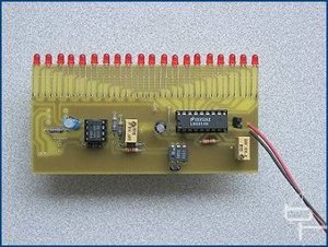
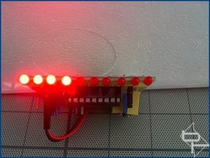
Time for the LEDs. I'll be using 5 superbright reds that I got from an LED cluster at Wal-Mart. You could use blue or whatever if you so desire.
First of all, find an un-used wall-wart and figure out the voltage it puts out. Then use Bit-Tech's own LED calculator to figure out the required resistor
http://www.bit-tech.net/article/68/


---
The plexi I used wasn't too thick (only 3mm) it was necessary to trim down the LEDs. You could do it the safe and patient way and use a file or sheet of sandpaper, but I won't cover that. Instead, I'll show you the magic of the bench grinder. It managed to take the LEDs down to size in a few seconds

---
Next up, we need to make grooves or channels for the wiring to fit through. Once again, we'll turn to our friend, the router for it's assistance. You can't really tell in the picture, but I carefully set the depth of cut so it's about 2mm deep. That way, I can safely cut a 2mm groove in the plexi, and use the other 1mm for support.

At this point I should mention that to mount the LEDs, I drilled 3/8" holes. Honest to goodness holes. Don't worry, they can't even be detected once the surface goes on.


---
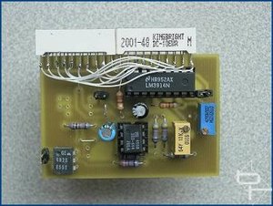
A film can is used to house the switchs and wiring. This holds many advantages, such as preventing electric shocks, and preventing 'fallapart'


---
Finally, the mouse tracking surface was from an old school book. I can't really describe the material or give it a name. It was hard, yet bendy. It is also quite low in the friction department, and it lets my mouse glide around freely. It also tracks very well in the optical department. I cut it out so that it was 1cm inset on every edge, and attached it with double sided carpet tape.
---
Finally, the result:


Light on ^^

Light off ^^

Hope this was semi-easy to follow and gave an even clearer understanding and insight into the process of making a mouse pad

HDD Activity Meter

bit-tech.net

Author: Dave Williams
Published: 23rd June 2002

A Knight in Shining LEDs
Okay, this circuit is really part of the "Knight Rider" project. I have separated it purely for the benefit of web search engines looking for a "Hard Drive Activity Meter". It uses the same basic circuit, circuit board designs and construction as before, and therefore I am not going to repeat all that detail. I strongly suggest you refer to the "Knight Rider" project for construction details.

This circuit is designed as a replacement for the standard HDD activity LED and offers an indication of the amount of activity by lighting a row of LEDs. The higher the HDD activity, the more LEDs light. It does not give a reading of actual Mb/s, just how hard the drive is working.

The circuit is based around the "Classic" Knight Rider design and differs only with R3 being fitted in it's alternate position, the addition of IC4 and R6, and VR1 is replaced with a wire link.

The opto-isolator, IC4, connects to the HDD LED header on the motherboard and serves to isolate the circuit from the rest of the system whilst ensuring compatibility with just about every motherboard that has a HDD LED. As the HDD reads and writes it produces a stream of pulses which are fed to the circuit via the opto-isolator. These pulses are fed into IC1b, which buffers and shapes these pulses before feeding them into IC1a. IC1a is an integrator whose job it is to "smooth" these pulses into a voltage level. This voltage is reasonably proportional to the frequency and duration of the pulses generated by the HDDs activity. Hence, the busier the drive, the higher the voltage. This voltage is fed from the output of IC1a into IC2 which is an LED bargraph voltmeter. So in a nutshell, the busier the drive, the more LEDs light up. Similar to the previous circuits, the display can be operated in either DOT or BAR mode and has 10 and 20 LED variations.

VR3 sets the "zero" and is adjusted so that all the LEDs are just extinguished with no HDD activity. VR2 is the "span" and is adjusted so that all the LEDs are lit during heavy or constant drive activity. This span adjustment is somewhat subjective and is found by trial and error during HDD activity.


HDD Activity Meter The Circuit


Parts List with order codes for UK and US suppliers
HDD Activity Meter The Circuit


10 individual LED version

This board design like the others following, uses R3 in it's alternate position and has additional components IC4 and R6. VR1 is also replaced with a wire link. These changes to the layout are denoted in red. This board has two links, one of which replaces VR1.


HDD Activity Meter The CircuitHDD Activity Meter The Circuit
Component layout - top view (left) and Track layout - Viewed from above (right)


HDD Activity Meter The Circuit
The finished board.


Single LED array version

Note the two links on the circuit board and that R3 is fitted in it's "alternate" position.

HDD Activity Meter The CircuitHDD Activity Meter The Circuit
Component layout - top view (left) and Track layout - Viewed from above (right)


HDD Activity Meter The CircuitHDD Activity Meter The Circuit

The finished board and the detail of how the anodes are linked together and connected to the board using pad13, indicated by the red

20 LED versions

In this design the effect is of a pair of LEDs moving away from each other, (DOT mode), or, if using BAR mode, a row of LEDs expanding outwards away from each other.

HDD Activity Meter 20 LED Versions


Parts List with order codes for UK and US suppliers
HDD Activity Meter 20 LED Versions


20 individual LED version

As in all the board designs for the HDD meter, R3 is fitted in its alternate position and VR1 is replaced with a wire link. There is a total of three links on this board.


HDD Activity Meter 20 LED Versions
Component layout - top view.


HDD Activity Meter 20 LED Versions
Track layout - Viewed from above.


HDD Activity Meter 20 LED Versions
The finished board.


The PCB layout if using two 10 LED arrays

Again three links are used here.


HDD Activity Meter 20 LED VersionsHDD Activity Meter 20 LED Versions

Component layout - top view (left) and Track layout - Viewed from above (right)


HDD Activity Meter 20 LED Versions
The finished board.


HDD Activity Meter 20 LED Versions
Wiring detail between the LED arrays viewed from above.

Setting up

HDD Activity Meter Setting Up

Setting up is simple but does involve a degree of trial and error. As before, I have included some resistance settings for VR2 and VR3 to give a reasonable starting point. Remember to set these measurements with the power disconnected from the circuit.

It helps to have the meter in BAR mode when setting up. With power connected and the HDD LED connection from the motherboard plugged in to the meter board, adjust VR3 so all the meter LEDs are just off. Then give the HDD something to do, I copied the pak0.pk3 file from the Quake 3 CD to my HDD. This file is 468MB and is big enough to allow sufficient time and constant HDD activity to set VR2. You can use any large file so long as it takes enough time to allow the setting of VR2. Whilst the file is copying adjust VR2 so all the LEDs are just fully lit.

Go back and check the VR3 setting and if needed readjust. If VR3 is readjusted then VR2 will also require tweaking. Keep repeating this fine tuning of the controls until no more adjustment is needed. The idea is to have no LEDs lit with no HDD activity and all LEDs lit, or the top LED in the case of using DOT mode, with constant drive activity. The in-between bits will look after themselves!


HDD Activity Meter Setting UpHDD Activity Meter Setting Up
Adjust VR3 so all the LEDs are just extinguished.


HDD Activity Meter Setting UpHDD Activity Meter Setting Up
VR2 is adjusted so that all LEDs are lit during constant drive activity.


The meter is an indication of the level of HDD activity, which can be influenced by operating system file caching, and as such, is somewhat subjective in how the display is interpreted. The component values used in the circuit produce excellent results with the motherboard/hard drive combinations tested but due to design variations between motherboards from different manufacturers, experimenting with the value of C2 may produce better/worse results. Values between 10uF - 100uF should be suitable.

The same comments about experimenting with the circuit made in the sister article here also apply to this design.

Electrónica

Donde Vem

Downloads

Murros no Estômago

Tecnologia IG Brasil

Baixaki - Downloads

Technow